 |
| October 08, 2019 | Volume 15 Issue 38 |
Designfax weekly eMagazine

Archives
Partners
Manufacturing Center
Product Spotlight
Modern Applications News
Metalworking Ideas For
Today's Job Shops
Tooling and Production
Strategies for large
metalworking plants
Engineer's Toolbox:
How to maximize retention of spring pins
By Evan Dowell, SPIROL Application Engineer
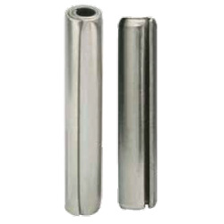
There are two types of spring pins: coiled pins (left) and slotted pins (right).
Spring pins are used in many different assemblies for a variety of reasons: to serve as hinge pins and axles, to align components, or simply to fasten multiple components together. Spring pins are formed by rolling and configuring a metal strip into a cylindrical shape that allows for radial compression and recovery. When properly implemented, Spring pins provide reliable, robust joints with excellent retention.
During installation, spring pins compress and conform to the smaller host hole. Work used to compress the pin has been captured as potential energy. The compressed pin then exerts outward radial force against the hole wall. Retention is provided by compression and the resultant friction between the pin and hole wall. For this reason, surface-area contact between the pin and the hole is critical.
Retention can be optimized by increasing radial stress and/or contact surface area. A larger, heavier pin will exhibit reduced flexibility and, as a result, the installed spring load or radial stress will be higher. Coiled spring pins are the exception to this rule as they are available in multiple duties (light, standard, and heavy) to provide a greater range of strength and flexibility within a given diameter.
There is a linear relationship between friction/retention and engagement length of a spring pin within a hole. Therefore, increasing the length of the pin and the resulting contact surface area between the pin and host hole will result in higher retention. In addition, considering there is no retention at the very end of the pin due to the chamfer, it is important to take the chamfer length into consideration when calculating engagement length. At no point should the pin's chamfer be located in the shear plane between mating holes, because this can lead to translation of tangential force into axial force that can contribute to "walking" or pin movement away from the shear plane until the force is neutralized (see Figure 1).
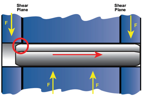
Figure 1: The pin's chamfer must not be in the shear plane. In this case, the pin will move in the direction indicated until the chamfer is no longer in the shear plane.
To avoid this scenario, it is recommended that the end of the pin clear the shear plane by a length equal to one pin diameter or more. This condition can also be caused by tapered holes that can similarly translate tangential force into outward movement. As such, it is recommended that holes with no taper be implemented, and if taper is necessary it remain under 1 degree included.
Spring pins will recover a portion of their pre-installed diameter wherever they are unsupported by the host material. In applications for alignment, it is recommended that the spring pin be inserted 60 percent of the total pin length into the initial hole to permanently fix its position and control the diameter of the protruding end (see Figure 2).
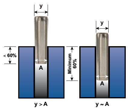
Figure 2: The example on the left shows how the protruding end of the pin maintains a diameter larger than the hole when less than 60 percent of the length is retained in the host hole. On the right, the protruding end of the pin has a diameter approximately equal to the hole.
In free-fit hinge applications, it is preferred to retain the pin in the outer members provided the width of each of these locations is greater than or equal to 1.5X the pin's diameter. If this guideline is not satisfied, retaining the pin in the center component may be prudent. Friction-fit hinges require all hinge components be prepared with matched holes and that each component, regardless of the number of hinge segments, maximizes engagement with the pin.
Although this article offers general design guidelines, it is recommended that SPIROL application engineers who specialize in fastening and joining be consulted to ensure the optimum design is employed for each application.
Want more information? Go to www.spirol.com.
Published October 2019
Rate this article
View our terms of use and privacy policy